|
.
.
.
.
.
.
.
.
.
.
.
.
.
.
.
.
.
.
.
.
.
.
.
.
.
.
.
.
.
.
.
.
.
.
.
.
|
Page 7
|
|
|
The Fundamental Operation
... |
Rack & Pinion
Orientation
for Backlash Elimination |
|

|
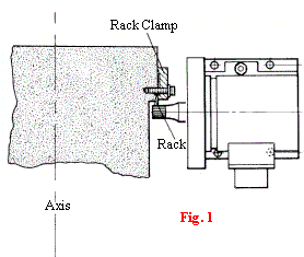
The movement of the rack is recorded by a pinion, which drives a
resolver/encoder (see fig.1). This is a non-contact system at the point
of converting a mechanical motion into an electronic position signal. In
any non-contacting measuring system a precision air gap must be
maintained between the moving member and the sensors.
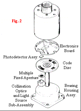
Our gap is within the rotating transducer
and accurately maintained by high quality bearings (see fig. 2)
|
|

|
|
It is easier to maintain
closer tolerances with instrument size components with small ABEC 7 ball
bearings than a large machine member with large bearings.
The point of mechanical contact is where the
pinion meshes with the rack pitch line. This mesh is controlled by the
unique flex plate mounting for encoder or resolver to less than one (1)
pound of force thus providing zero backlash (0.00010" repeatability) and
low reading errors with up to 0.010" misalignment between fixed and
moving members of the machine yet negligible rack to pinion wear. |
|
|
<<<Back |
Page 7 |
 Next
Page>>> Next
Page>>> |
|
|
5143 Electric Avenue
Hillside, IL 60162
708-449-5700 (Phone)
708-449-5703 (Fax)
E-Mail: schlenkent@aol.com
|
|
[Rack_and_Pinion_Measuring]
[Precision_Rules] [DROs] [AC_Servo_Motors]
[Instrument_Gears] [Clutches,_Brakes]
[Torque_Transducers]
[Products] [Contact_Us-Send_Brochure]
[Home] |
|
Best viewed in Microsoft Internet
Explorer or Netscape Communicator.
Best viewed in a 600 X 800 monitor.
Copyright © 1998 Schlenker
Enterprises Ltd. |


